Archive for Arduino

ProtoThread 协程复习笔记

近一年没用 ProtoThread 了,忘得差不多了。这次搞硬件密码器重新学习了下,同时记录下来笔记,方便下次使用。

ProtoThread 是一个资源占用极少的多线程协程库,可以在51、avr等资源极其有限的硬件上面运行。

ProtoThread 有几种实现方式,这里只考虑存c switch 实现。这个实现其实就是用1byte存放当前执行到的位置,下次恢复这个线程的时候通过 switch 跳转到上次执行的位置继续执行。每个线程就只占用2byte存放当前位置(当前代码行号)即可。伪代码:

 
//线程结构体
struct pt {
  unsigned short lc;   // 当前线程执行到的位置(行号)
};
PT_THREAD(f1(struct pt *pt))
// 展开宏后的代码
// char f1(struct pt *pt)
{
    // 这里可以写每次任务切换进来都执行的代码    
    //  注意,只有静态变量才能正确的保存,非静态变量在切换协程时会丢失
    // 同样,静态变量的限制使得一个函数不能多协程同时执行,局部变量会冲突。
    static int a;

   PT_BEGIN(pt);  // 准备协程环境
    // 展开宏后的代码:
    // char PT_YIELD_FLAG = 1;
   //  switch(pt.lc) { case 0;
   // 等待至条件达成
    // 可以看到,是通过记录当前执行位置后直接退出函数来实现的让出cpu。
    // 恢复执行时通过 switch 的 case 跳转回上次执行的位置来实现的恢复执行。
    PT_WAIT_UNTIL(pt, 条件);
    // 展开后的代码:
    /*
  do {
    (pt)->lc =  __LINE__;
     case __LINE__:;
    if(!(condition)) {
      return PT_WAITING;  
    }
  } while(0)
   */
   PT_END(pt); // 结束协程环境
    // 展开后的代码:
    // };
    // PT_YIELD_FLAG = 0;
    // pt.lc=0;
    // return PT_ENDED;
}
void main()
{
    struct pt p1;    // 线程1
    struct pt p2;   // 线程2
   //初始化线程
    PT_INIT(&p1); // 其实就是 p1.lc = 0
    PT_INIT(&p2); 
   while(1)
    {
      /// 启动两个线程
      f1(&p1); 
      f1(&p2);        
    }
}

这种实现的几个特点:
• 纯c实现,无硬件依赖,方便移植
• 不能在函数内再次使用switch
• 资源占用极少,每线程仅占用2字节
• 支持阻塞操作,没有栈的切换
• 运行在单一c函数中,无法跨函数是用。弥补措施是被调用函数也写成单独的Protothread
• 线程切换时不保存局部变量,弥补措施是使用静态局部变量,造成单个函数不能多线程同时执行。另一个弥补措施是实现自己的 pt 结构,将需要保存的局部变量保存到 pt 结构里面。

附几个函数:
PT_INIT(pt) 初始化任务变量,只在初始化函数中执行一次就行
PT_BEGIN(pt) 启动任务处理,放在函数开始处
PT_END(pt) 结束任务,放在函数的最后
PT_WAIT_UNTIL(pt, condition) 等待某个条件(条件可以为时钟或其它变量,IO等)成立,否则直接退出本函数,下一次进入本 函数就直接跳到这个地方判断
PT_WAIT_WHILE(pt, cond) 和上面一个一样,只是条件取反了
PT_WAIT_THREAD(pt, thread) 等待一个子任务执行完成
PT_SPAWN(pt, child, thread) 新建一个子任务,并等待其执行完退出
PT_RESTART(pt) 重新启动某个任务执行
PT_EXIT(pt) 任务后面的部分不执行,直接退出重新执行
PT_YIELD(pt) 锁死任务
PT_YIELD_UNTIL(pt, cond) 锁死任务并在等待条件成立,恢复执行
在pt中一共定义四种线程状态,在任务函数退出到上一级函数时返回其状态
PT_WAITING 等待
PT_EXITED 退出
PT_ENDED 结束
PT_YIELDED 锁死

(下面的是定时器,该宏是 http://www.cnblogs.com/xiaowuyi/p/4319720.html 写的,用之前请在#include “pt.h” 的前面,前面啊!加上一句#define PT_USE_TIMER)

先说明一下,下面的定时不一定完全准确的,可能会有点点的误差,可能偏后。如果遇上了很烦的任务,有可能会使延时延后。但是正常情况下,直接用就好了。

如果要很精确的延时,请用delay语句或者计时器,但是,绝大多数情况下,绝大多数情况!绝大多数情况!请用下面的语句代替delay延时!这样才能把CPU让给别的任务使用。

PT_TIMER_DELAY(pt,延时毫秒数);
字面上的意思,不用多说了吧?最大值约为49.7天,估计没人会延时辣么久吧……

PT_TIMER_MICRODELAY(pt,延时微秒数);
字面上的意思,不用多说了吧?注意,最小精度与arduino的版本有关,与micros()有精度一致。

PT_TIMER_WAIT_TIMEOUT(pt,条件,毫秒数);
如果条件成立了,或者超时了,就继续运行,否则切换任务。

要用的话,请在#include “pt.h”前面加上一句 #define PT_USE_SEM

首先要创建一个信号量,这个一定是全局变量:
static struct pt_sem 信号量名;

接着请在setup()函数里面给它初始化:
PT_SEM_INIT(&信号量名,数量);
信号量名前面有个&,别忘了。数量就相当于停车场的总车位数。

然后要用啦。任务要停一辆车进去:
PT_SEM_WAIT(pt,&信号量名);
信号量名前面有个&,别忘了。一个语句只能停一辆车,土豪好多车就用多次。

任务要开一辆车出来:
PT_SEM_SIGNAL(pt,&信号量名);
信号量名前面有个&,别忘了。用一次出一辆。

参考:
• http://dunkels.com/adam/pt/
• Protothread机制文档 http://blog.csdn.net/tietao/article/details/8507455
• 一个“蝇量级” C 语言协程库 http://coolshell.cn/articles/10975.html
• ProtoThreads http://blog.csdn.net/utopiaprince/article/details/6041385
No comment »

python 与 arduino 串口通信

 
>>> import serial
>>> ser = serial.Serial(8)
>>> ser.timeout=1
>>> ser.close()
>>> ser = serial.Serial(8)
>>> ser.timeout=1
>>> ser.readline()
''
>>> ser.write("11111\n")   # 每个命令以 \n 结尾
6L
>>> ser.readline()
'received: 11111\r\n'
>>> ser.write("11111\n")
6L
>>> ser.write("22222\n33333333\n") # 可以一次发送多个命令,同样以 \n 结尾。
15L
>>> ser.readline()
'received: 11111\r\n'
>>> ser.readline()
'received: 22222\r\n'
>>> ser.readline()
'received: 33333333\r\n'
>>> ser.readline()
''
>>> 
 
char serial_line[100] ="";
int serial_line_length=0;

void setup()
{
  Serial.begin(9600);
  Serial.setTimeout(1000); //串口超时 1000 毫秒
}

void loop()
{
  if (Serial.available() > 0)
  {
    // 读取,读到\n或100字符或超时
    serial_line_length = Serial.readBytesUntil('\n', serial_line, 100);
    serial_line[serial_line_length ]='\0';    // 截断字符串
    Serial.print("received: ");
    Serial.println(serial_line);
  }
}

参考:
http://www.geek-workshop.com/thread-5733-1-1.html
http://wiki.geek-workshop.com/doku.php?id=arduino:arduino_language_reference:serial
http://pythonhosted.org//pyserial/pyserial_api.html

No comment »

ARDUINO 最小系统

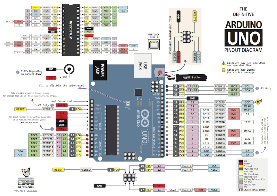
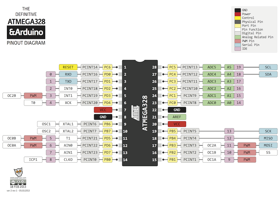
atmeg328 内置复位电路,不需要外接复位电路。虽然也有内置晶振,但是 ARDUINO 只支持 16M 或 8M 的频率,所以最小系统还得用 16M 晶振接到9、10口(XTAL1、XTAL2),然后再分别接2个22p的电容到地就可以了。

全新的 atmeg328 没有 ARDUINO 的bootloader(引导程序) ,得用 IPS 接口写进去。之后就可以用串口写程序了。
熔丝位之类的设置不用管,ARDUINO IDE 写bootloader时会自动设置。对了,ARDUINO 的“使用编程器下载”功能会清除 ARDUINO 的bootloader(引导程序),除非资源太紧张,不建议使用。

如果需要复位按钮,可以用一个10K上拉电阻接到1(RESET)脚,然后弄个按钮,一端接到地,一段也接到1(RESET)脚。

还有一个问题,atmeg328 有两个 VCC 口(一个是 A/D 转换器的电源,这个必须接,不然芯片跑不起来,各个脚都是0.5V电压),建议都接到电源上面,如果只接7脚的 VCC ,会悲剧的跑不起来… 今天一上午都弄这个问题了。

附参考:
ARDUINO_V2

atmega328w

Arduino_Uno_Rev3-schematic

No comment »

Arduino 下 Nokia 5110 LCD + DS18B20 多点测温

温度库:http://milesburton.com/Dallas_Temperature_Control_Library
5110库:https://github.com/adafruit/Adafruit-PCD8544-Nokia-5110-LCD-library

资料上显示 DS18B20 可以使用 3-5v 电源供电,可以做到9-12位精度。不过12位精度比9位精度测温慢多了。而1820只能5V供电,9位精度。

 
/*********************************************************************
This is an example sketch for our Monochrome Nokia 5110 LCD Displays

  Pick one up today in the adafruit shop!
  ------> http://www.adafruit.com/products/338

These displays use SPI to communicate, 4 or 5 pins are required to
interface

Adafruit invests time and resources providing this open source code,
please support Adafruit and open-source hardware by purchasing
products from Adafruit!

Written by Limor Fried/Ladyada  for Adafruit Industries.
BSD license, check license.txt for more information
All text above, and the splash screen must be included in any redistribution
*********************************************************************/

#include 
#include 
#include "floatToString.h"

#include 
#include 

// pin 7 - Serial clock out (SCLK)
// pin 6 - Serial data out (DIN)
// pin 5 - Data/Command select (D/C)
// pin 4 - LCD chip select (CS)
// pin 3 - LCD reset (RST)
// pin2 - DS18B20  需要4.7k欧上拉电阻
Adafruit_PCD8544 display = Adafruit_PCD8544(7, 6, 5, 4, 3);

#define NUMFLAKES 10
#define XPOS 0
#define YPOS 1
#define DELTAY 2


#define LOGO16_GLCD_HEIGHT 16
#define LOGO16_GLCD_WIDTH  16

static unsigned char PROGMEM logo16_glcd_bmp[] =
{ B00000000, B11000000,
  B00000001, B11000000,
  B00000001, B11000000,
  B00000011, B11100000,
  B11110011, B11100000,
  B11111110, B11111000,
  B01111110, B11111111,
  B00110011, B10011111,
  B00011111, B11111100,
  B00001101, B01110000,
  B00011011, B10100000,
  B00111111, B11100000,
  B00111111, B11110000,
  B01111100, B11110000,
  B01110000, B01110000,
  B00000000, B00110000 };


// Data wire is plugged into port 2 on the Arduino
#define ONE_WIRE_BUS 2
#define TEMPERATURE_PRECISION 12

// Setup a oneWire instance to communicate with any OneWire devices (not just Maxim/Dallas temperature ICs)
OneWire oneWire(ONE_WIRE_BUS);

// Pass our oneWire reference to Dallas Temperature. 
DallasTemperature sensors(&oneWire);

// arrays to hold device addresses
DeviceAddress insideThermometer, outsideThermometer;


void setup()   {
  Serial.begin(9600);

  display.begin();
  // init done

  // you can change the contrast around to adapt the display
  // for the best viewing!
  display.setContrast(50);

  display.display(); // show splashscreen
  
  
  // Start up the library
  sensors.begin();

  // locate devices on the bus
  Serial.print("Locating devices...");
  Serial.print("Found ");
  Serial.print(sensors.getDeviceCount(), DEC);
  Serial.println(" devices.");
    // set the resolution to 12 bit
  sensors.setResolution( TEMPERATURE_PRECISION);


  // draw a single pixel
  display.drawPixel(10, 10, BLACK);
  display.display();
  delay(2000);
  
  
}

//char buffer[25];// floatToString
//char s[25];// floatToString


void loop() {
  
    Serial.print("Requesting temperatures...");
  sensors.requestTemperatures();
  Serial.println("DONE");
  

  display.clearDisplay();   // clears the screen and buffer

//  float tempC = sensors.getTempCByIndex(0);
//  floatToString(buffer, tempC, 2);
//  Serial.println("Temp C: ");
//  Serial.print(tempC);
//sprintf(s,"c:%s",buffer);

  // text display tests
  display.setTextSize(1);
  display.setTextColor(BLACK);
  display.setCursor(0,0);
  display.print("c0:");
  display.println(sensors.getTempCByIndex(0));
  display.print("c1:");
  display.println(sensors.getTempCByIndex(1));
  display.print("c2:");
  display.println(sensors.getTempCByIndex(2));
  display.display();
  delay(2000);


}

注意,需要使用arduino-1.52以上版本,arduino-1.05的会出现以下错误:

\arduino-1.0.5-windows\arduino-1.0.5\libraries\Robot_Control\ArduinoRobot.cpp: In constructor 'RobotControl::RobotControl()':
\arduino-1.0.5-windows\arduino-1.0.5\libraries\Robot_Control\ArduinoRobot.cpp:8: error: 'LCD_CS' was not declared in this scope
\arduino-1.0.5-windows\arduino-1.0.5\libraries\Robot_Control\ArduinoRobot.cpp:8: error: 'DC_LCD' was not declared in this scope
\arduino-1.0.5-windows\arduino-1.0.5\libraries\Robot_Control\ArduinoRobot.cpp:8: error: 'RST_LCD' was not declared in this scope
\arduino-1.0.5-windows\arduino-1.0.5\libraries\Robot_Control\ArduinoRobot.cpp: In member function 'void RobotControl::begin()':
\arduino-1.0.5-windows\arduino-1.0.5\libraries\Robot_Control\ArduinoRobot.cpp:18: error: 'MUXA' was not declared in this scope
\arduino-1.0.5-windows\arduino-1.0.5\libraries\Robot_Control\ArduinoRobot.cpp:18: error: 'MUXB' was not declared in this scope
\arduino-1.0.5-windows\arduino-1.0.5\libraries\Robot_Control\ArduinoRobot.cpp:18: error: 'MUXC' was not declared in this scope
\arduino-1.0.5-windows\arduino-1.0.5\libraries\Robot_Control\ArduinoRobot.cpp:18: error: 'MUXD' was not declared in this scope
\arduino-1.0.5-windows\arduino-1.0.5\libraries\Robot_Control\ArduinoRobot.cpp:19: error: 'MUX_IN' was not declared in this scope
\arduino-1.0.5-windows\arduino-1.0.5\libraries\Robot_Control\ArduinoRobot.cpp:22: error: 'BUZZ' was not declared in this scope
\arduino-1.0.5-windows\arduino-1.0.5\libraries\Robot_Control\ArduinoRobot.cpp:25: error: 'Serial1' was not declared in this scope

No comment »